Description
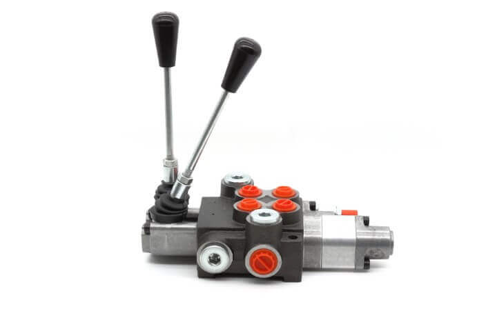
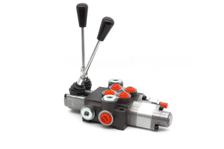
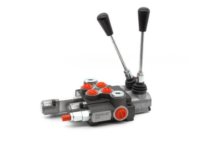
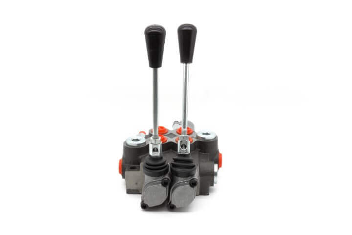
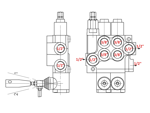
Description: Manually or mechanically controlled hydraulic directional control valve is designed for distribution and control of working fluid between generator (pump) and executive mechanisms (cylinder, hydro-motor, etc.). It is manufactured with 2 plungers, with parallel connection, with common check valve for each plunger and with safety valve. Position number 3 on section 2 (check below) is used to allow attached cylinder to float freely. Hydraulic fluid can float freely between each sides of cylinder piston (from port A to port B) thus allowing it to be adjusted to outside forces. This kind of feature is called floating feature. Mostly this feature is used for snow pushers or snow plowers.
Construction: Valve is made out on single block (monoblock). Its body is made of cast iron EN-GJL-300. Plungers are made of carbonized steel with hard chrome plating.
Features:
Type of hydraulic valve: Hydraulic Monoblock Valve with floating position
Type of control: Hydraulic Hand Valve
Nominal flow: 40 l/min
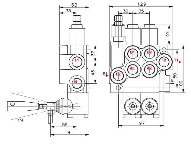
Number of sections: 2
Number of handles: 2
Internal valves connection system: parallel (also called independent, because internal valve in each section of this monoblock valve is functioning independently of each other)
Safety valve: Included
Mounting: 2 diagonal M8 holes
Ambient temperature: -40°C…+60°C
Fluid medium: Mineral oil based hydraulic oil
Viscosity:
- 12…800 mm²/s permissible range
- 20…100 mm²/s recommended range
Fluid temperature: -15°C…+80°C
Filtration: class 10 according NAS 1638
Max operating pressure:
- P = 250 bar
- T = 50 bar
- A,B = 300 bar
Internal leakage: 7 cm³/min at 100 bar
Spool stroke: 6 mm
Actuating force: < 200 N in spool axis direction
Numbering of sections:
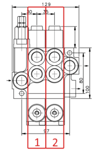
Section 1 (3 positions):
Section 2 (4 positions, position number 3 is floating position):
